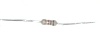
Resistor

Resistor

What is Resistor

Resistor is an electrical component that reduces the electric current.
The resistor's ability to reduce the current is called resistance and is measured in units of ohms (symbol: Ω).
If we make an analogy to water flow through pipes, the resistor is a thin pipe that reduces the water flow.

Ohm's law

The resistor's current I in amps (A) is equal to the resistor's voltage V in volts (V)
divided by the resistance R in ohms (Ω):

The resistor's power consumption P in watts (W) is equal to the resistor's current I in amps (A)
times the resistor's voltage V in volts (V):
P = I × V

The resistor's power consumption P in watts (W) is equal to the square value of the resistor's current I in amps (A)
times the resistor's resistance R in ohms (Ω):
P = I 2 × R

The resistor's power consumption P in watts (W) is equal to the square value of the resistor's voltage V in volts (V)
divided by the resistor's resistance R in ohms (Ω):
P = V 2 / R

Resistors in parallel
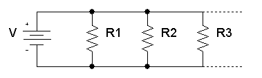
The total equivalent resistance of resistors in parallel RTotal is given by:

So when you add resistors in parallel, the total resistance is decreased.

Resistors in series
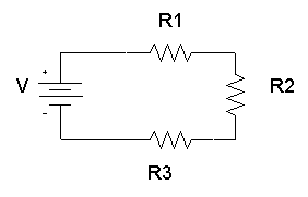
The total equivalent resistance of resistors in series Rtotal is the sum of the resistance values:
Rtotal = R1+ R2+ R3+...

So when you add resistors in series, the total resistance is increased.

Dimensions and material affects

The resistance R in ohms (Ω) of a resistor is equal to the resistivity ρ in ohm-meters (Ω∙m) times the resistor's length l in meters (m) divided by the resistor's cross sectional area A in square meters (m2):
R=\rho \times \frac{l}{A}

Resistor image

Resistor symbols

resistor symbolResistor (IEEE)Resistor reduces the current flow.
resistor symbolResistor (IEC)
potentiomemer symbolPotentiometer (IEEE)Adjustable resistor - has 3 terminals.
potentiometer symbolPotentiometer (IEC)
variable resistor symbolVariable Resistor / Rheostat (IEEE)Adjustable resistor - has 2 terminals.
variable resistor symbolVariable Resistor / Rheostat (IEC)
Trimmer ResistorPresest resistor
ThermistorThermal resistor - change resistance when temperature changes
Photoresistor / Light dependent resistor (LDR)Changes resistance according to light

Resistor color code

The resistance of the resistor and its tolerance are marked on the resistor with color code bands that denotes the resistance value.
There are 3 types of color codes:
  • 4 bands: digit, digit , multiplier, tolerance.
  • 5 bands: digit, digit, digit , multiplier, tolerance.
  • 6 bands: digit, digit, digit , multiplier, tolerance, temperature coefficient.

Resistance calculation of 4 bands resistor

R = (10×digit1 + digit2) × multiplier

Resistance calculation of 5 or 6 bands resistor

R = (100×digit1 + 10×digit2+digit3) × multiplier

Resistor types

Variable resistorVariable resistor has an adjustable resistance (2 terminals)
PotentiometerPotentiometer has an adjustable resistance (3 terminals)
Photo-resistorReduces resistance when exposed to light
Power resistorPower resistor is used for high power circuits and has large dimensions.
Surface mount
(SMT/SMD) resistor
SMT/SMD resistors have small dimensions. The resistors are surface mounted on the printed circuit board (PCB), this method is fast and requires small board area.
Resistor networkResistor network is a chip that contains several resistors with similar or different values.
Carbon resistor 
Chip resistor 
Metal-oxide resistor 
Ceramic resistor 

Pull-up resistor

In digital circuits, pull-up resistor is a regular resistor that is connected to the high voltage supply (e.g +5V or +12V) and sets the input or output level of a device to '1'.
The pull-up resistor set the level to '1' when the input / output is disconnected. When the input / output is connected, the level is determined by the device and overrides the pull-up resistor.

Pull-down resistor

In digital circuits, pull-down resistor is a regular resistor that is connected to the ground (0V) and sets the input or output level of a device to ' 0 '.
The pull-down resistor set the level to ' 0 ' when the input / output is disconnected. When the input / output is connected, the level is determined by the device and overrides the pull-down resistor.

Electrical Units

Electrical Units

Electrical Units

Electrical & electronic units of electric current, voltage, power, resistance, capacitance, inductance, electric charge, electric field, magnetic flux, frequency:
  • Electrical & electronic units table
  • Units prefix table
  • Electrical units definitions

Electrical & electronic units table

Unit NameUnit SymbolQuantity
Ampere (amp)AElectric current (I)
VoltVVoltage (V, E)
Electromotive force (E)
Potential difference (Δφ)
OhmΩResistance (R)
WattWElectric power (P)
Decibel-milliwattdBmElectric power (P)
Decibel-WattdBWElectric power (P)
Volt-Ampere-ReactivevarReactive power (Q)
Volt-AmpereVAApparent power (S)
FaradFCapacitance (C)
HenryHInductance (L)
siemens / mhoSConductance (G)
Admittance (Y)
CoulombCElectric charge (Q)
Ampere-hourAhElectric charge (Q)
JouleJEnergy (E)
Kilowatt-hourkWhEnergy (E)
Electron-volteVEnergy (E)
Ohm-meterΩ∙mResistivity (ρ)
siemens per meterS/mConductivity (σ)
Volts per meterV/mElectric field (E)
Newtons per coulombN/CElectric field (E)
Volt-meterV⋅mElectric flux (Φe)
TeslaTMagnetic field (B)
GaussGMagnetic field (B)
WeberWbMagnetic flux (Φm)
HertzHzFrequency (f)
SecondssTime (t)
Meter / metremLength (l)
Square-meterm2Area (A)
DecibeldB 
Parts per millionppm 

Units prefix table

Prefix

Prefix
Symbol
Prefix
factor
Example
picop10-121pF = 10-12F
nanon10-91nF = 10-9F
microμ10-61μA = 10-6A
millim10-31mA = 10-3A
kilok10 31kΩ = 1000Ω
megaM10 61MHz = 106Hz
gigaG10 91GHz = 109Hz


Electrical units definitions

Volt (V)

Volt is the electrical unit of voltage.
One volt is the energy of 1 joule that is consumed when electric charge of 1 coulomb flows in the circuit.
1V = 1J / 1C

Ampere (A)

Ampere is the electrical unit of electrical current. It measures the amount of electrical charge that flows in an electrical circuit per 1 second.
1A = 1C / 1s

Ohm (Ω)

Ohm is the electrical unit of resistance.
1Ω = 1V / 1A

Watt (W)

Watt is the electrical unit of electric power. It measures the rate of consumed energy.
1W = 1J / 1s
1W = 1V ⋅ 1A

Decibel-milliwatt (dBm)

Decibel-milliwatt or dBm is a unit of electric power, measured with logarithmic scale referenced to 1mW.
10dBm = 10 ⋅ log10(10mW / 1mW)

Decibel-Watt (dBW)

Decibel-watt or dBW is a unit of electric power, measured with logarithmic scale referenced to 1W.
10dBW = 10 ⋅ log10(10W / 1W)

Farad (F)

Farad is the unit of capacitance. It represents the amount of electric charge in coulombs that is stored per 1 volt.
1F = 1C / 1V

Henry (H)

Henry is the unit of inductance.
1H = 1Wb / 1A

siemens (S)

siemens is the unit of conductance, which is the opposite of resistance.
1S = 1 / 1Ω

Coulomb (C)

Coulomb is the unit of electric charge.
1C = 6.238792×10¹⁸ electron charges

Ampere-hour (Ah)

Ampere-hour is a unit of electric charge.
One ampere-hour is the electric charge that flow in electrical circuit, when a current of 1 ampere is applied for 1 hour.
1Ah = 1A ⋅ 1hour
One ampere-hour is equal to 3600 coulombs.
1Ah = 3600C

Tesla (T)

Tesla is the unit of magnetic field.
1T = 1Wb / 1m2

Weber (Wb)

Weber is the unit of magnetic flux.
1Wb = 1V ⋅ 1s

Joule (J)

Joule is the unit of energy.
1J = 1 kg ⋅ m2 / s2

Kilowatt-hour (kWh)

Kilowatt-hour is a unit of energy.
1kWh = 1kW ⋅ 1h = 1000W ⋅ 1h

Kilovolt-amps (kVA)

Kilovolt-amps is a unit of power.
1kVA = 1kV ⋅ 1A = 1000 ⋅ 1V ⋅ 1A

Hertz (Hz)

Hertz is the unit of frequency. It measures the number of cycles per second.
1 Hz = 1 cycles / s


Ohm (symbol Ω) is the electrical unit of resistance

Ohm (symbol Ω) is the electrical unit of resistance

Ohm (Ω)

Ohm (symbol Ω) is the electrical unit of resistance.
The Ohm unit was named after George Simon Ohm.
1Ω = 1V / 1A = 1J ⋅ 1s / 1C2

Table of resistance values of Ohm

namesymbolconversionexample
milli-ohmmΩ1mΩ = 10-3ΩR0 = 10mΩ
ohmΩ
-
R1 = 10Ω
kilo-ohmkΩ1kΩ = 103ΩR2 = 2kΩ
mega-ohmMΩ1MΩ = 106ΩR3 = 5MΩ

Ohmmeter

Ohmmeter is a measurement device that measures resistance.
Superconductivity

Superconductivity

Conductors lose all of their electrical resistance when cooled to super-low temperatures (near absolute zero, about -273° Celsius). It must be understood that superconductivity is not merely an extrapolation of most conductors’ tendency to gradually lose resistance with decreasing temperature; rather, it is a sudden, quantum leap in resistivity from finite to nothing. A superconducting material has absolutely zero electrical resistance, not just some small amount.
Superconductivity was first discovered by H. Kamerlingh Onnes at the University of Leiden, Netherlands, in 1911. Just three years earlier, in 1908, Onnes had developed a method of liquefying helium gas, which provided a medium with which to supercool experimental objects to just a few degrees above absolute zero. Deciding to investigate changes in electrical resistance of mercury when cooled to this low of a temperature, he discovered that its resistance dropped to nothing just below the boiling point of helium.
There is some debate over exactly how and why superconducting materials superconduct. One theory holds that electrons group together and travel in pairs (called Cooper pairs) within a superconductor rather than travel independently, and that has something to do with their frictionless flow. Interestingly enough, another phenomenon of super-cold temperatures, superfluidity, happens with certain liquids (especially liquid helium), resulting in frictionless flow of molecules.
Superconductivity promises extraordinary capabilities for electric circuits. If conductor resistance could be eliminated entirely, there would be no power losses or inefficiencies in electric power systems due to stray resistances. Electric motors could be made almost perfectly (100%) efficient. Components such as capacitors and inductors, whose ideal characteristics are normally spoiled by inherent wire resistances, could be made ideal in a practical sense. Already, some practical superconducting conductors, motors, and capacitors have been developed, but their use at this present time is limited due to the practical problems intrinsic to maintaining super-cold temperatures.
The threshold temperature for a superconductor to switch from normal conduction to superconductivity is called the transition temperature. Transition temperatures for “classic” superconductors are in the cryogenic range (near absolute zero), but much progress has been made in developing “high-temperature” superconductors which superconduct at warmer temperatures. One type is a ceramic mixture of yttrium, barium, copper, and oxygen which transitions at a relatively balmy -160° Celsius. Ideally, a superconductor should be able to operate within the range of ambient temperatures, or at least within the range of inexpensive refrigeration equipment.
The critical temperatures for a few common substances are shown here in this table. Temperatures are given in kelvins, which has the same incremental span as degrees Celsius (an increase or decrease of 1 kelvin is the same amount of temperature change as 1° Celsius), only offset so that 0 K is absolute zero. This way, we don’t have to deal with a lot of negative figures.
MaterialElement/AlloyCritical temp.(K)
AluminumElement1.20
CadmiumElement0.56
LeadElement7.2
MercuryElement4.16
NiobiumElement8.70
ThoriumElement1.37
TinElement3.72
TitaniumElement0.39
UraniumElement1.0
ZincElement0.91
Niobium/TinAlloy18.1
Cupric sulphideCompound1.6
Superconducting materials also interact in interesting ways with magnetic fields. While in the superconducting state, a superconducting material will tend to exclude all magnetic fields, a phenomenon known as the Meissner effect. However, if the magnetic field strength intensifies beyond a critical level, the superconducting material will be rendered non-superconductive. In other words, superconducting materials will lose their superconductivity (no matter how cold you make them) if exposed to too strong of a magnetic field. In fact, the presence of any magnetic field tends to lower the critical temperature of any superconducting material: the more magnetic field present, the colder you have to make the material before it will superconduct.
This is another practical limitation to superconductors in circuit design, since electric current through any conductor produces a magnetic field. Even though a superconducting wire would have zero resistance to oppose current, there will still be a limit of how much current could practically go through that wire due to its critical magnetic field limit.
There are already a few industrial applications of superconductors, especially since the recent (1987) advent of the yttrium-barium-copper-oxygen ceramic, which only requires liquid nitrogen to cool, as opposed to liquid helium. It is even possible to order superconductivity kits from educational suppliers which can be operated in high school labs (liquid nitrogen not included). Typically, these kits exhibit superconductivity by the Meissner effect, suspending a tiny magnet in mid-air over a superconducting disk cooled by a bath of liquid nitrogen.
The zero resistance offered by superconducting circuits leads to unique consequences. In a superconducting short-circuit, it is possible to maintain large currents indefinitely with zero applied voltage!
rings of superconducting material
Rings of superconducting material have been experimentally proven to sustain continuous current for years with no applied voltage. So far as anyone knows, there is no theoretical time limit to how long an unaided current could be sustained in a superconducting circuit. If you’re thinking this appears to be a form of perpetual motion, you’re correct! Contrary to popular belief, there is no law of physics prohibiting perpetual motion; rather, the prohibition stands against any machine or system generating more energy than it consumes (what would be referred to as an over-unity device). At best, all a perpetual motion machine (like the superconducting ring) would be good for is to store energy, not generate it freely!
Superconductors also offer some strange possibilities having nothing to do with Ohm’s Law. One such possibility is the construction of a device called a Josephson Junction, which acts as a relay of sorts, controlling one current with another current (with no moving parts, of course). The small size and fast switching time of Josephson Junctions may lead to new computer circuit designs: an alternative to using semiconductor transistors.
REVIEW:
  • Superconductors are materials which have absolutely zero electrical resistance.
  • All presently known superconductive materials need to be cooled far below ambient temperature to superconduct. The maximum temperature at which they do so is called the transition temperature.
From Electric to Electronic

From Electric to Electronic

Introduction

This third volume of the book series Lessons In Electric Circuits makes a departure from the former two in that the transition between electric circuits and electronic circuits is formally crossed. Electric circuits are connections of conductive wires and other devices whereby the uniform flow of electric charges occurs. Electronic circuits add a new dimension to electric circuits in that some means of control is exerted over the flow of electric charges by another electrical signal, either a voltage or a current.

Electronic Circuits

In and of itself, the control of electric charge flow is nothing new to the student of electric circuits. Switches control the flow of electric charges, as do potentiometers, especially when connected as variable resistors (rheostats). Neither the switch nor the potentiometer should be new to your experience by this point in your study. The threshold marking the transition from electric to electronic, then, is defined by how the flow of electric charges is controlled rather than whether or not any form of control exists in a circuit. Switches and rheostats control the flow of electric charges according to the positioning of a mechanical device, which is actuated by some physical force external to the circuit. In electronics, however, we are dealing with special devices able to control the flow of electric charges according to another flow of electric charges, or by the application of a static voltage. In other words, in an electronic circuit, electricity is able to control electricity.

History of the Modern Electronics Era

Thomas Edison

The historic precursor to the modern electronics era was invented by Thomas Edison in 1880 while developing the electric incandescent lamp. Edison found that a small current passed from the heated lamp filament to a metal plate mounted inside the vacuum envelope. (Figure below (a)) Today this is known as the “Edison effect”. Note that the battery is only necessary to heat the filament. Electrons would still flow if a non-electrical heat source was used.
Edison effect, Fleming valve or vacuum diode, DeForest audion triode vacuum tube amplifier.

Vacuum Diode

By 1904 Marconi Wireless Company adviser John Flemming found that an externally applied current (plate battery) only passed in one direction from filament to plate (Figure above (b)), but not the reverse direction (not shown). This invention was the vacuum diode, used to convert alternating currents to DC. The addition of a third electrode by Lee DeForest (Figure above (c)) allowed a small signal to control the larger electron flow from filament to plate.

Audion Tube

Historically, the era of electronics began with the invention of the Audion tube, a device controlling the flow of an electron stream through a vacuum by the application of a small voltage between two metal structures within the tube. A more detailed summary of so-called electron tube or vacuum tube technology is available in the last chapter of this volume for those who are interested.

Transistor

Electronics technology experienced a revolution in 1948 with the invention of the transistor. This tiny device achieved approximately the same effect as the Audion tube, but in a vastly smaller amount of space and with less material. Transistors control the flow of electric charges through solid semiconductor substances rather than through a vacuum, and so transistor technology is often referred to as solid-state electronics.